

Cut Cycle Time – Mold Better Parts
IMS Select Exclusive Spiral™ End Caps, Screw Tips,
R-Screws and Hoppers will help you do both!
Logarithmic spiral curves promote a faster, freer flow of material than conventional, flat tapers. A smoother, unencumbered flow produces better parts. These facts are why IMS incorporates spiral curves in each component of it’s exclusive SPIRAL™ System. The following is a brief history of how the IMS SPIRAL™ System developed.
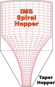
Watch this 30 second video to see how much faster material
passes through the Spiral (right) versus Conical (left) Hopper.
The introduction of electronic process controls back in the early 1980’s was without a doubt a technological breakthrough. For a lot of OTHER industries this was a huge step forward. For the injection molding industry, however, IMS questioned the logic of trying to computerize a process so full of variables and lacking in standardization.
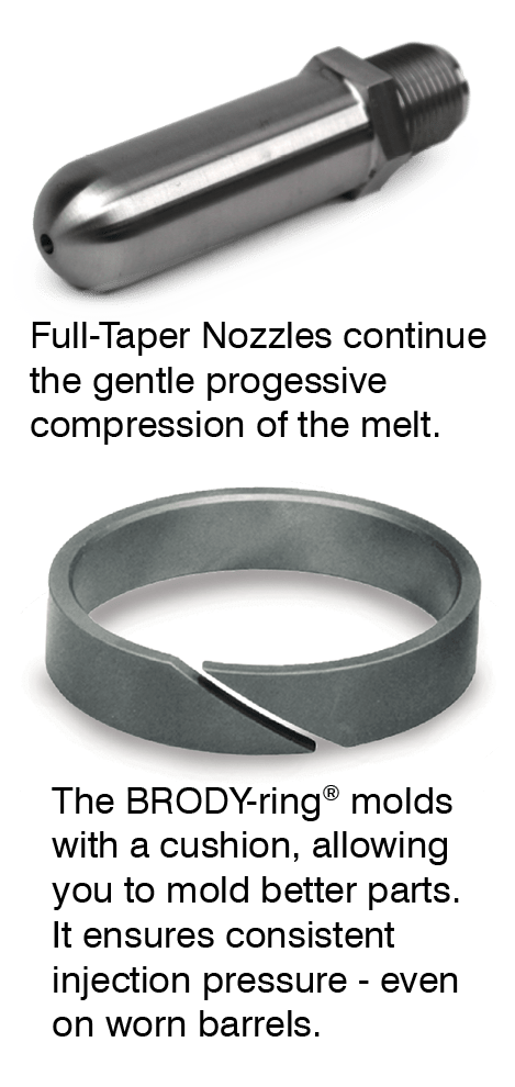
Prior to process controls, IMS had developed numerous individual products aimed specifically at improving part quality. Full Taper Nozzles and Screw Tip BRODY-Rings® are just a couple of examples. Each addressed a specific need and they all remain solid, successful products. It was the emergence of process control, however, that really started us thinking about the injection process as a whole (both the machinery and the material) and what could and should be changed in order to mold better parts.
It was already a proven fact that the current, restrictive R-Screw Process was stretching and deforming the molecular bonds of our plastics and seriously affecting finished part strength. We needed to find ways to get the plastic from the hopper to the mold with the least amount of damage possible. We found that this problem could be solved, in large part, by the replacement of all standard, flat internal tapers with smoother, gentler, logarithmic spiral curves.

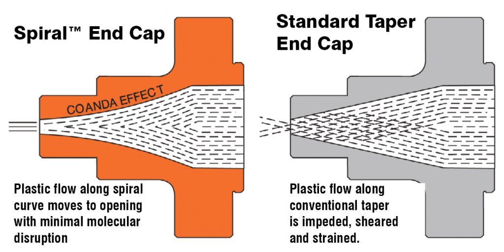
The more gradual compressing of the material, plus the resulting coanda effect (that is, the phenomenon of material flow tending to follow closely along the wall contour of a passage), greatly eased the strain on the plastic’s molecules and the effects on the material’s inherent properties.
A. In 1986, IMS first used this technology in the development of their revolutionary Spiral™ End Caps. The results, as projected, were impressive. Parts were stronger and more dimensionally stable. Older presses equipped with these new end caps were actually producing higher quality parts than new presses with traditional style caps.

Without Damage to the Molecular Structure.
B. Next IMS focused its attention on the Screw Tip. Their existing melt valves with narrow sliding ring and anti-blow- by BRODY-Ring® seal were already proven effective at maintaining shot control. But it was the development, in 1988, of a unique, Spiral™ front end that made IMS Spiral™ Screw Tips the least restrictive tips ever produced. The reduction of strains, flow lines and shear-induced heat in the melt improved part strength and quality significantly.
Another innovation was the introduction of the Thermally Compensated R-Screw. Research showed that installation of a heat tube in the front end of the screw would effectively transfer excess heat from the compression zone back to the transition zone, where it could be reused to assist in the melting of incoming pellets. Screw wear from unmelted pellets was dramatically reduced and the ability to turn down front end heat had a direct and positive effect on cycle time, part quality and reject rate.
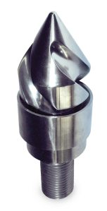
Easy-Flow (Spiral-Discharge) Screw Tips with Brody-Ring®
Advance the Melt Without Strains or Shelter Heat
C. Next step, the feed hopper. No matter what their diameter or height, they all had the same straight taper to the machine intake. At least that’s the way it was prior to 1988. Consequently, they were all prone to bridging and surging. There wasn’t a single OEM feed hopper that could guarantee consistent, even feeding of the pellets to the screw. IMS found that a logarithmic Spiral Curve in place of the straight taper produced astounding results. Tests showed that whether the material was virgin or regrind, or whether the hopper was full or nearly empty, all the material moved all the time in a steady downward flow. Hence, IMS Spiral™ Hopper was born. Their effect on part weight, part dimensions, and overall part consistency, not to mention the flowability of most stubborn materials, is remarkable.

D. Finally IMS Spiral Technology was applied to the screw – more specifically, the screw flights. With IMS Spiral™ R-Screws:
- Pellets move forward in a more controlled, gentle tumble.
- Pellets begin melting sooner and proceed in a far more efficient and orderly manner.
- Pressure is provided by the lateral movement of the screw (as it should be) – NOT by the compressing of the material by the screw flights, as is the case with all existing injection screws.
Nearly 30 years since the introduction of the reciprocating screw, the IMS Spiral™ R-Screw was the First and Only screw developed expressly to reduce molded-in stress and strain. Research has revealed the injection machine doesn’t work as hard and produces more consistent quality parts.
IMS Exclusive Spiral™ Retrofit Components can improve the IMS Exclusive Spiral™ Retrofit Components can improve the performance of any injection press regardless of age, make, or model. They can also significantly increase your bottom line. Inquire today for more information!
When a Spiral Hopper is Likely a Better Choice
You should strongly consider a Spiral Hopper if:
- You run mixed batches or often operate with hopper partly full (versus maintaining full inventory).
- Materials are challenging: regrind, irregular shapes, high moisture sensitivity, etc.
- Your quality control is tight: need shot-to-shot consistency, minimal defects from pellet feeding issues.
- Productivity is critical, and cycle times are being impacted by material feed inconsistencies.
- You’re willing to invest a bit more up front for better performance and less downstream defects / maintenance.
When Conical Hopper Might Be Enough (or Preferable)
- If you run with hopper nearly always full, with flowable, “easy” materials.
- When initial cost or capital constraints are tight.
- Simpler operations where the benefit from Spiral design won’t offset the cost.
- If you have existing equipment and retrofitting or replacing hoppers is difficult or costly.


Leave a comment